Upgrading the QNAP TS-470 NAS - Processor and RAM
Shopping List:
1. QNAP TS-470 NAS - http://www.amazon.com/QNAP-TS-470-4-Bay-iSCSI-10GbE-ready/dp/B00EE18MZG/ref=sr_1_1?ie=UTF8&qid=1402894956&sr=8-1&keywords=qnap+ts-470
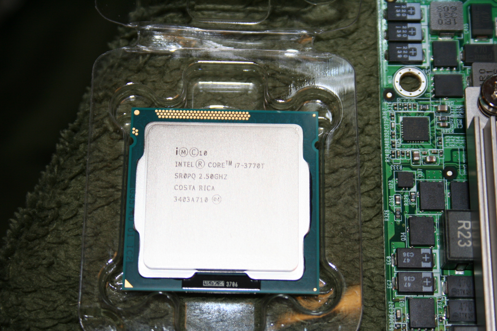
2. Intel 3770T I7 processor -
http://www.amazon.com/gp/product/B008ACVF9A/ref=oh_details_o00_s00_i00?ie=UTF8&psc=1
3. Arctic Silver 5 cpu grease - http://www.amazon.com/Arctic-Silver-Thermal-Compound-Grams/dp/B000OGX5AM/ref=sr_1_1?ie=UTF8&qid=1402895001&sr=8-1&keywords=arctic+5
4. Arcticlean solution - http://www.amazon.com/ArctiClean-60ml-Kit-30ml/dp/B0007TOR08/ref=pd_sim_pc_8?ie=UTF8&refRID=0AZZ21BF4KSY1ASJ1J36
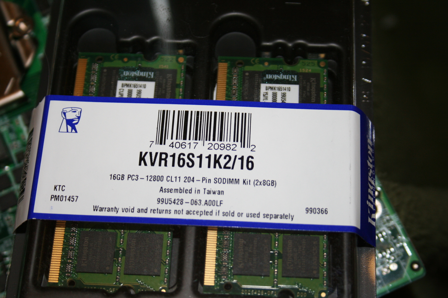
5. 16 gigs SO-DIMM memory - http://www.amazon.com/gp/product/B008TYIEVQ/ref=oh_details_o04_s00_i00?ie=UTF8&psc=1
Before Upgrading:
I would recommend that if you are upgrading a brand new NAS you want to make sure it is working before you crack the case. Doing this upgrade will VOID you warranty so you don't want to upgrade a broken box only to find out after the upgrade. Therefore I installed the latest firmware to QTS 4.1.x, installed my SSD's, created volumes and copied data back and forth to the NAS. Very limited testing but I knew before I started the upgrade that the box booted, the back-plane worked and the network cards worked.
Here is how I did the upgrade:
1.
Remove all hard drives before starting.
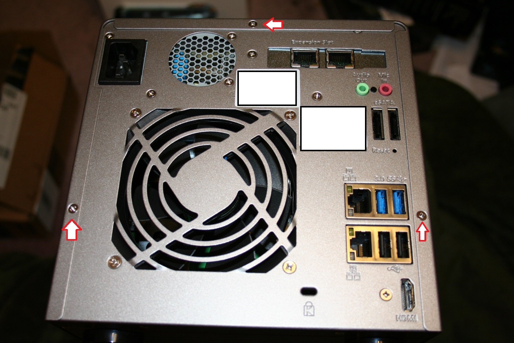
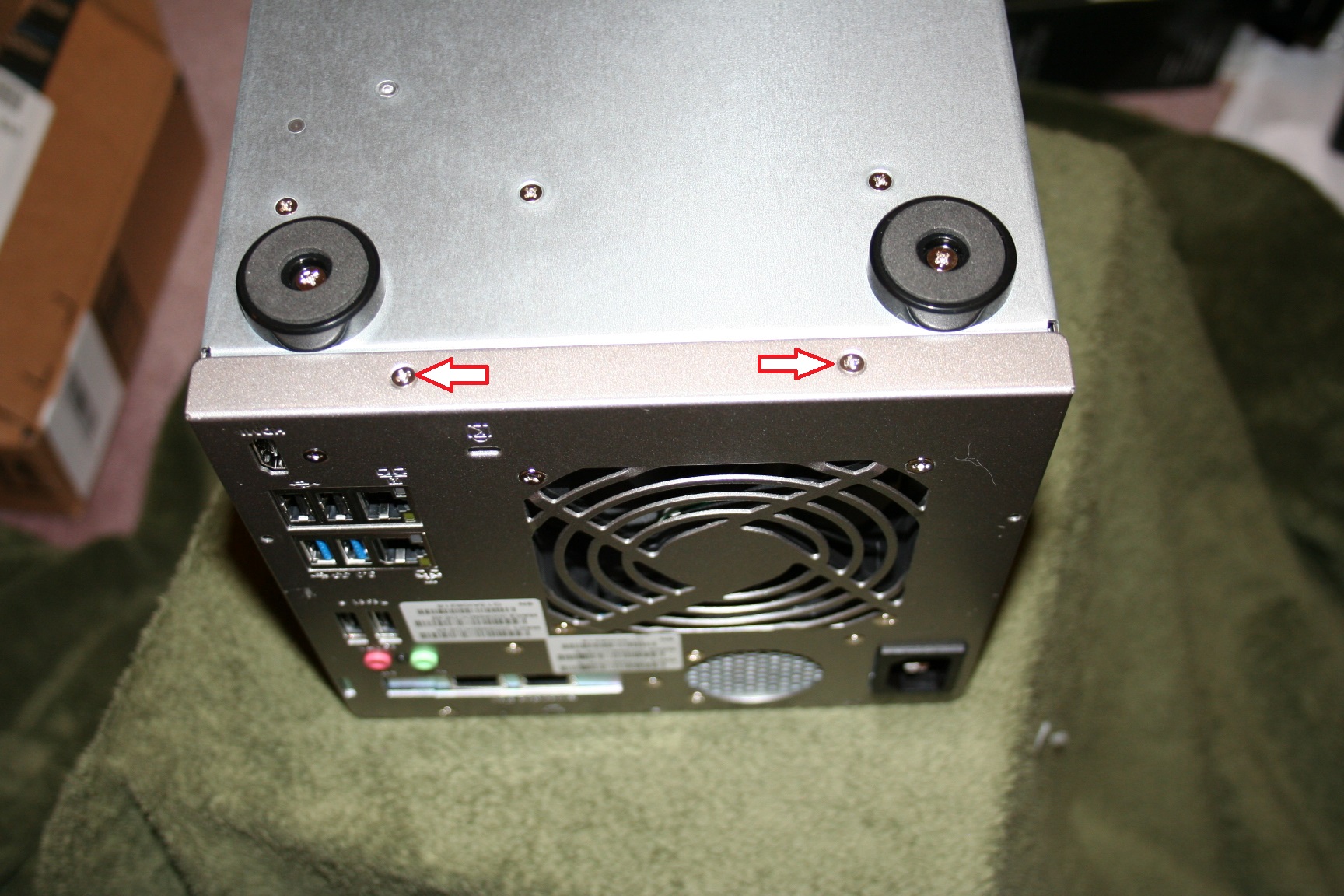
2.
Remove
the 3 screws on the back side of the device picture below.
Pry the cover back by inserting a flat head screw driver under the lip of
the cover and gently work the screw driver around, if you don't keep moving the
screw driver you will end up bending the list. Keep working the screw
driver until the cover moves back freely and then lift the cover off.
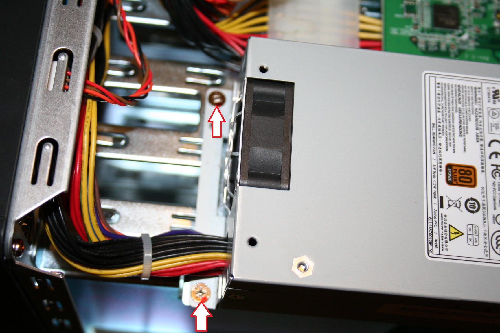
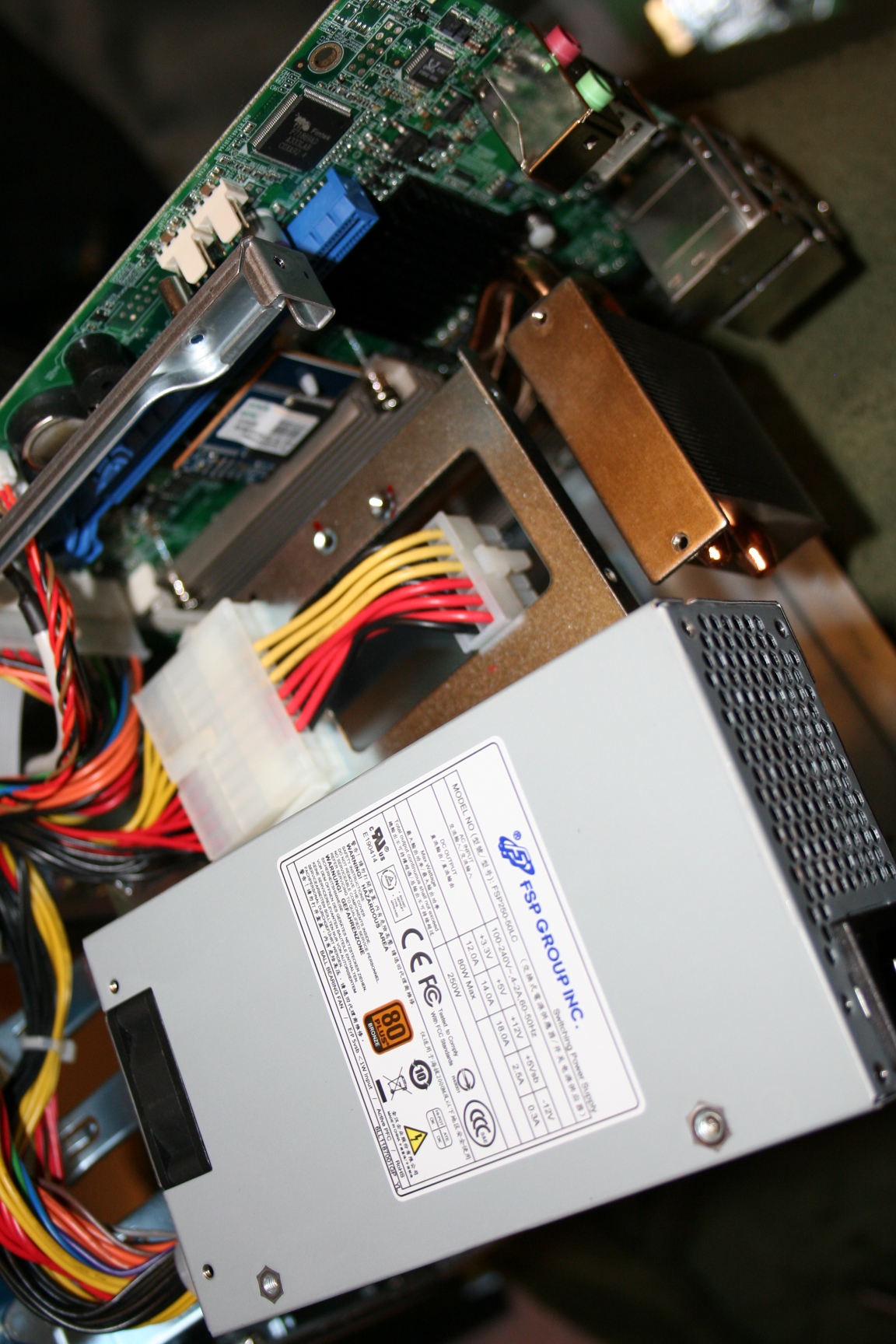
3.
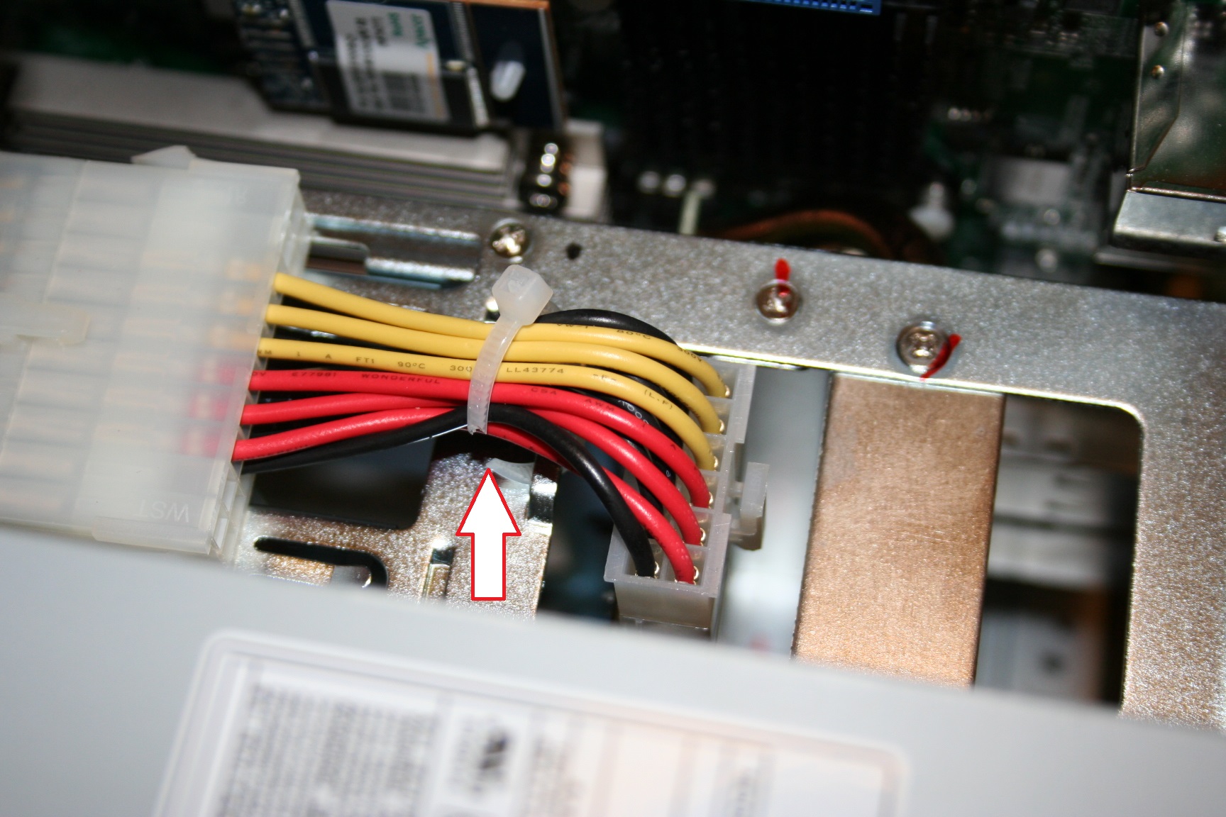
Next remove the screws for the power supply and
the screw holding in the network adapter.
Once the screws are removed you can move the power supply to then unplug
the network card. Pictures below.
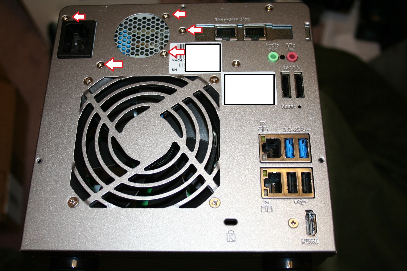
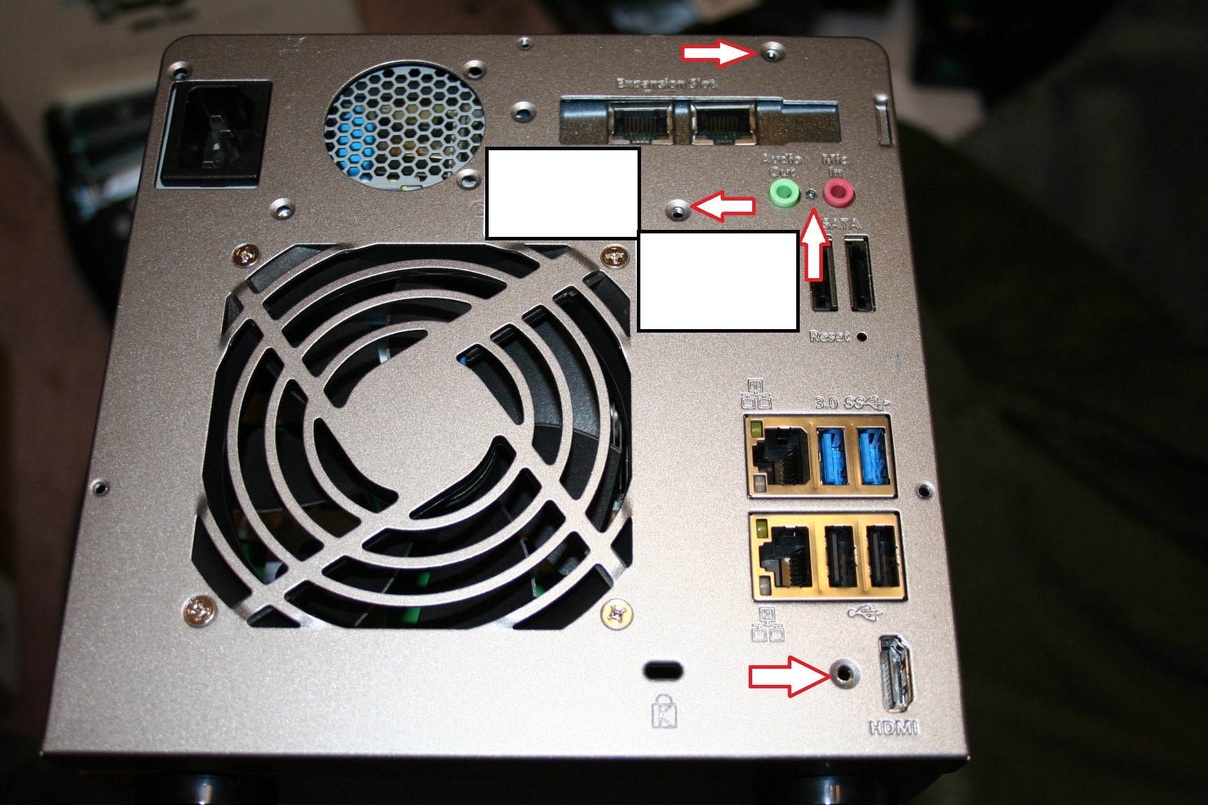
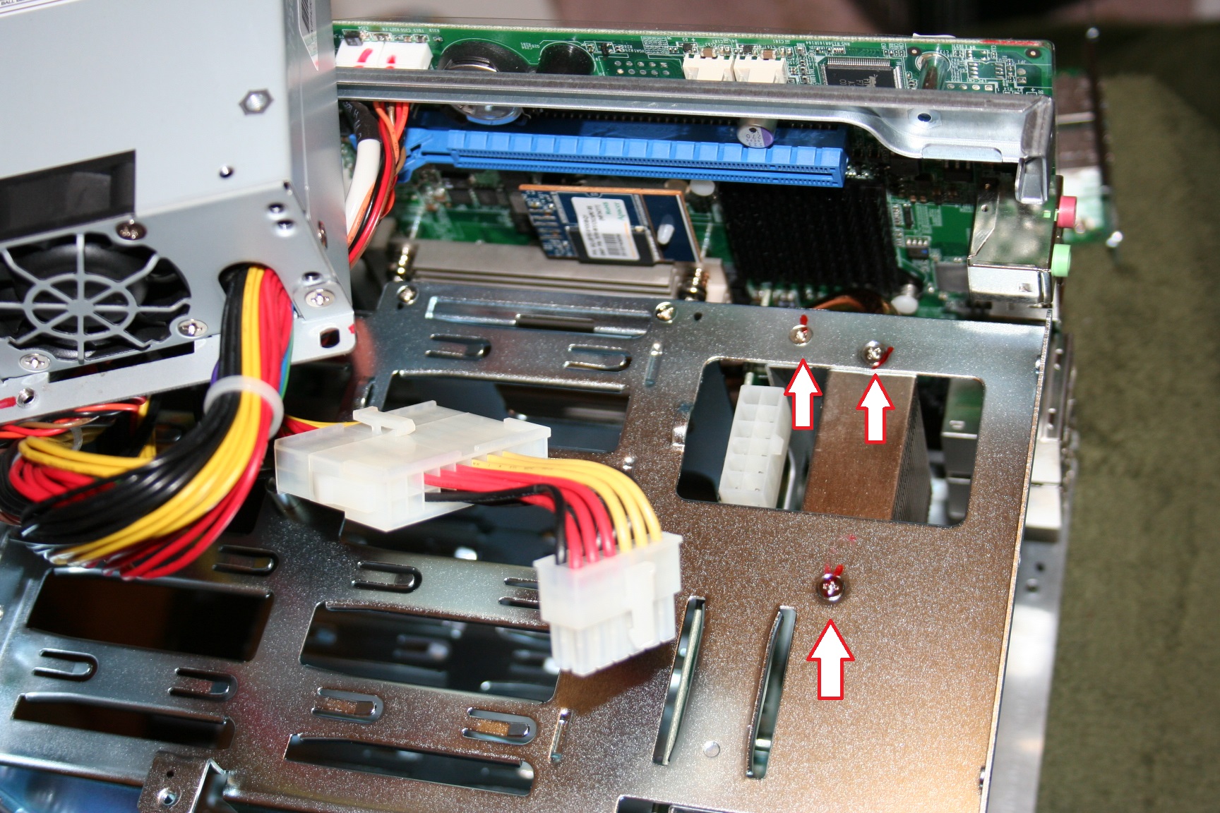
4.
Remove
the rest of the screws in the back panel.
You will need a really small Philips screwdriver to remove the black
screw between the audio connectors.
Remove the screws on the side of the back panel and the screws on the bottom of
the back panel as pictured below.
5.
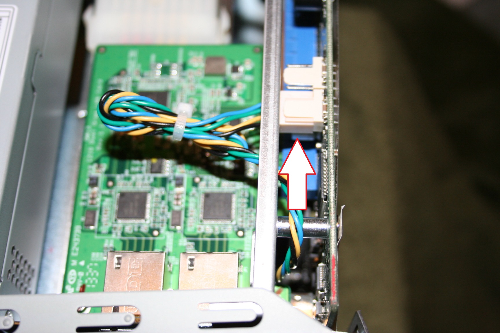
Unplug
the fan and then remove the back cover completely.
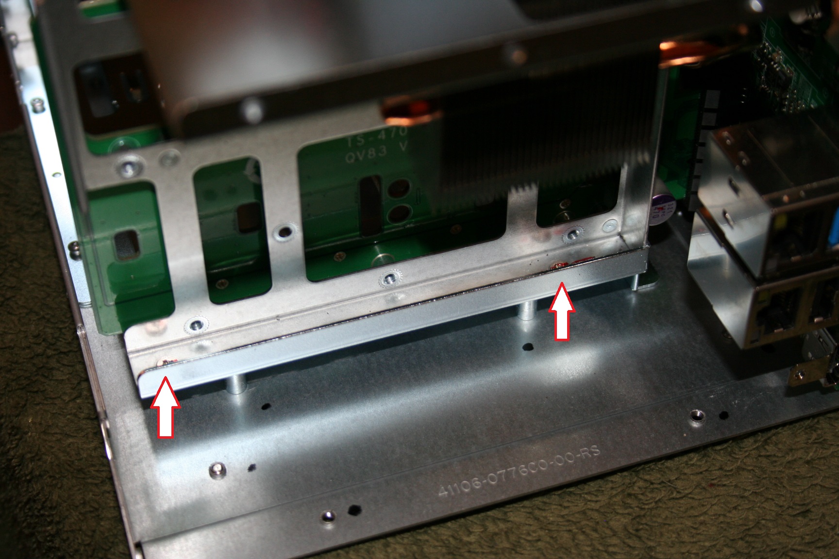
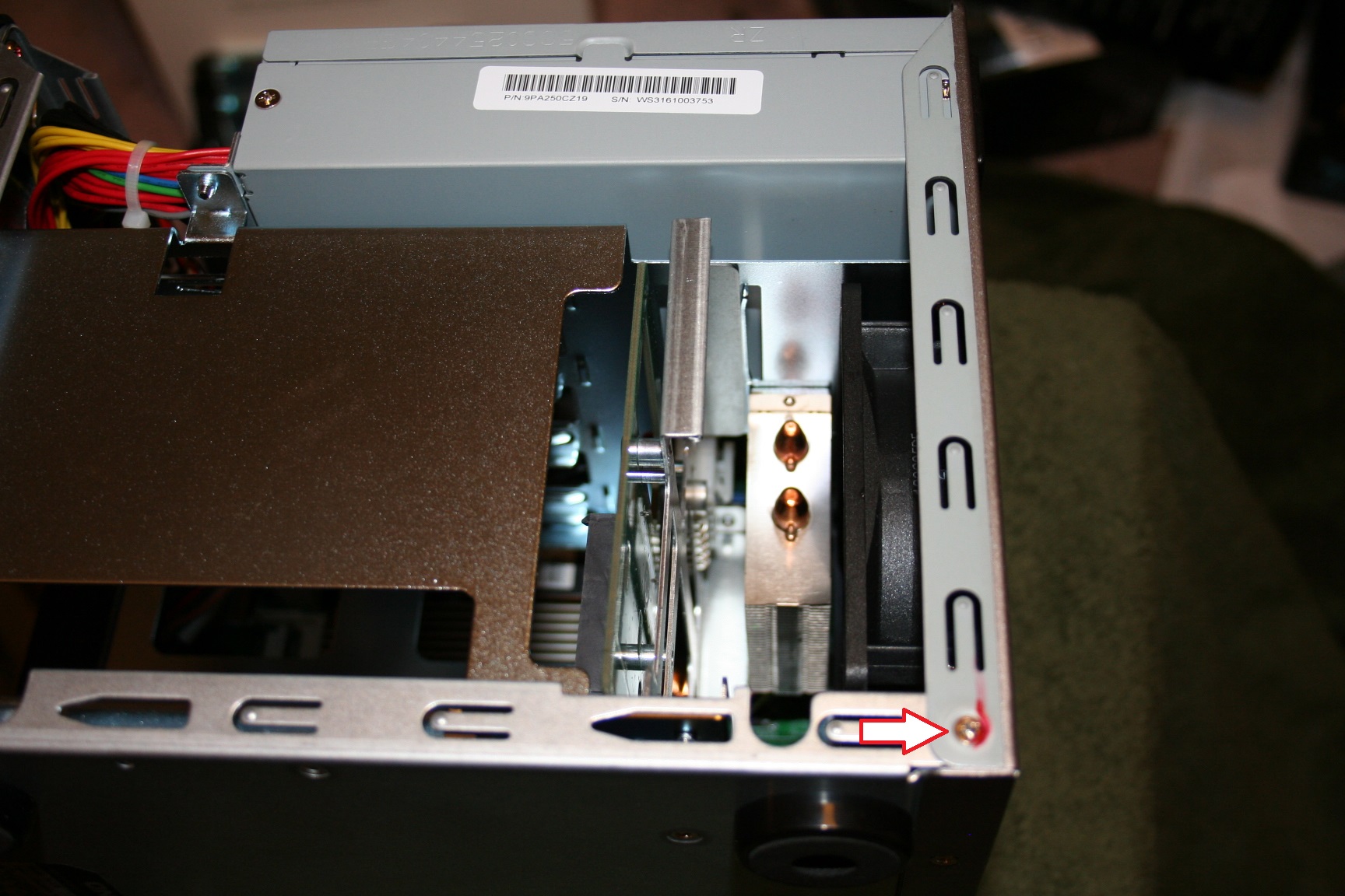
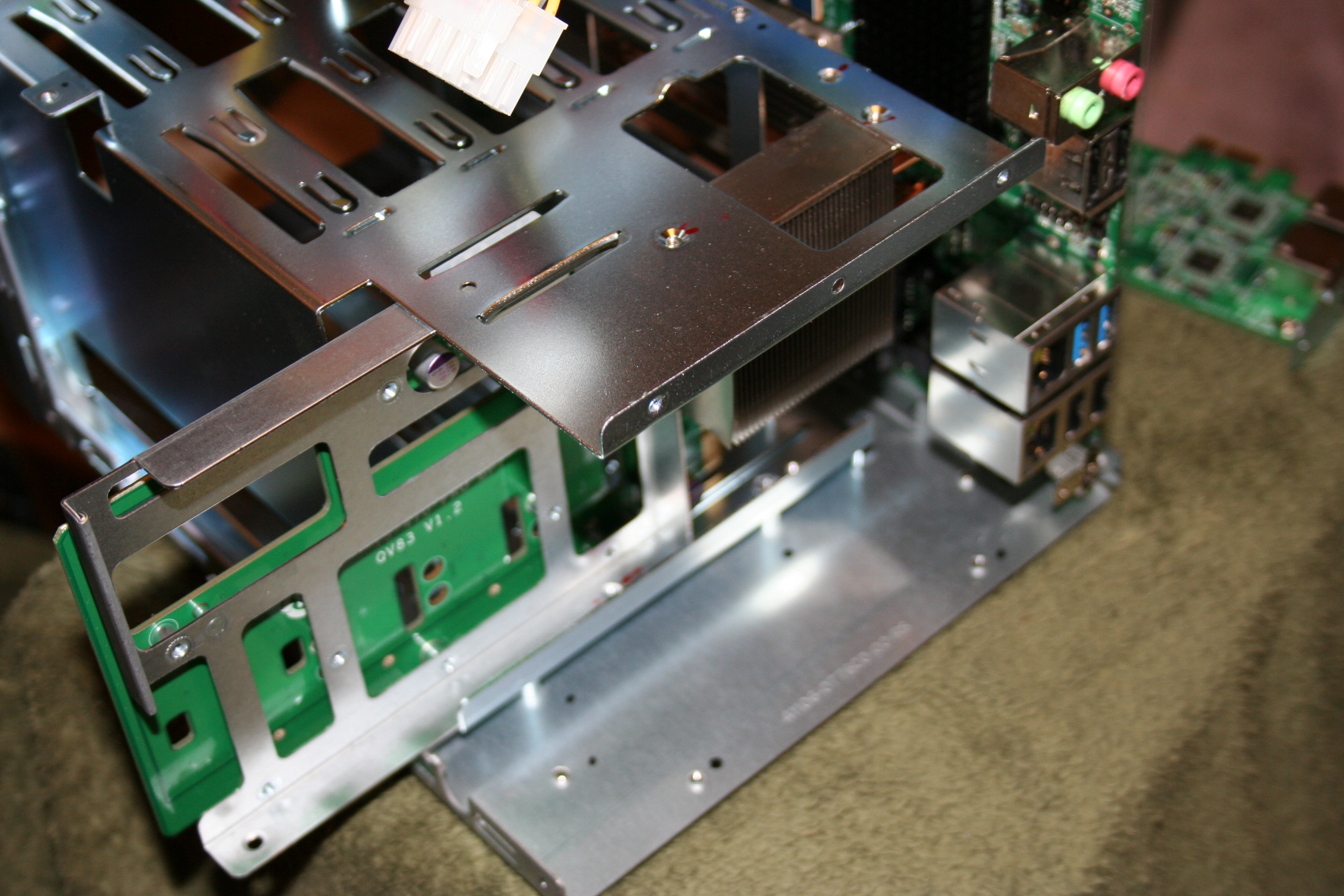
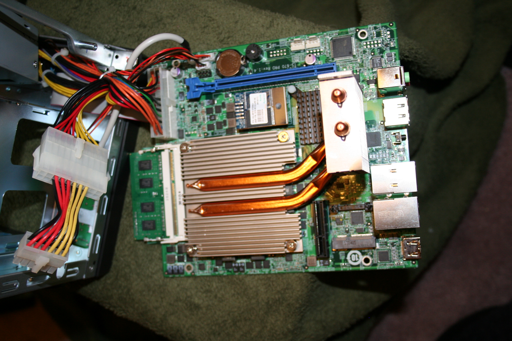
10.
Slide the back plain out.
11.
Remove
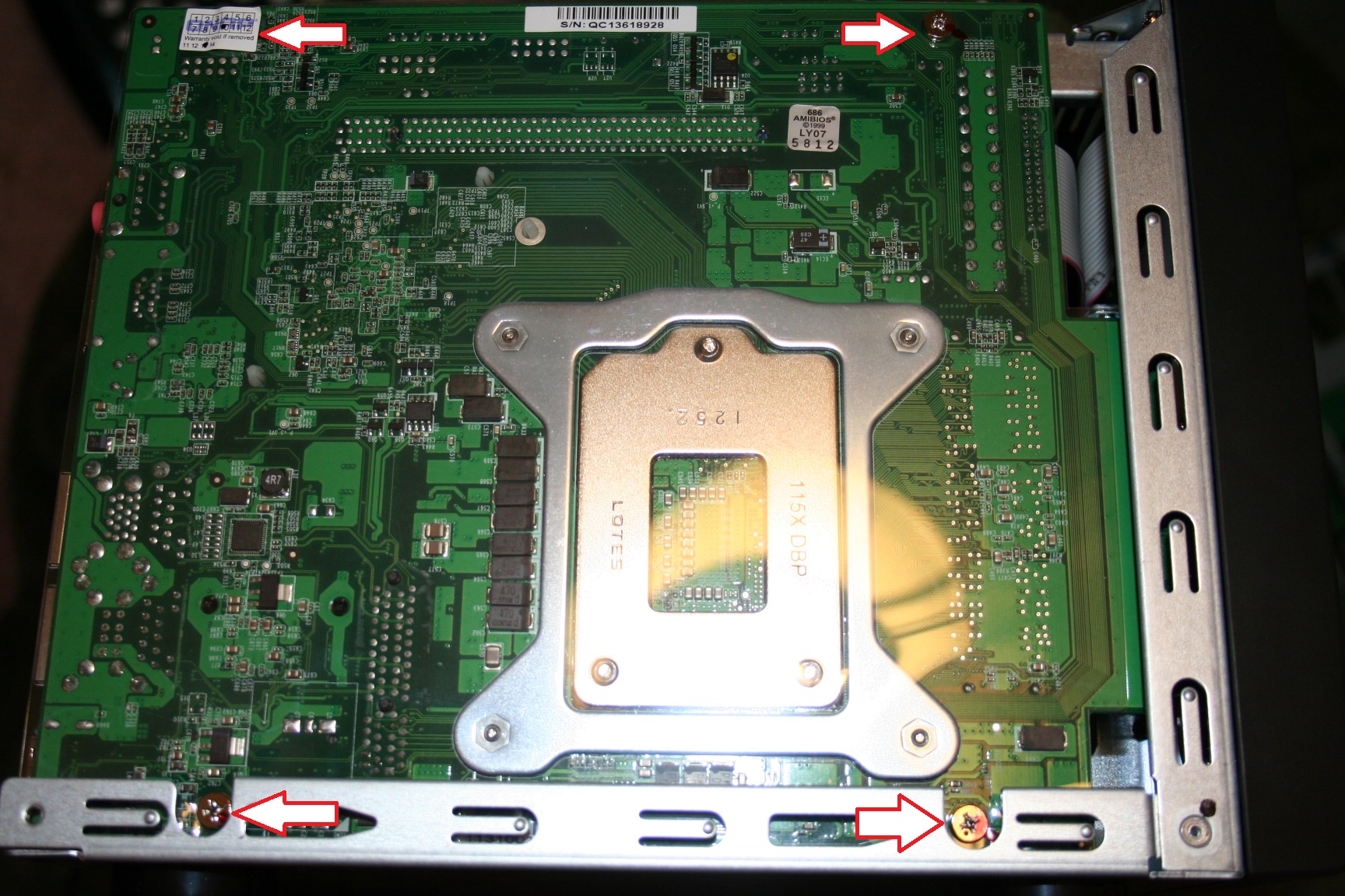
the 4 screws holding in the motherboard.
The upper left is covered with a warranty sticker.
Once that is removed there is no going back.
Your warranty will be void.
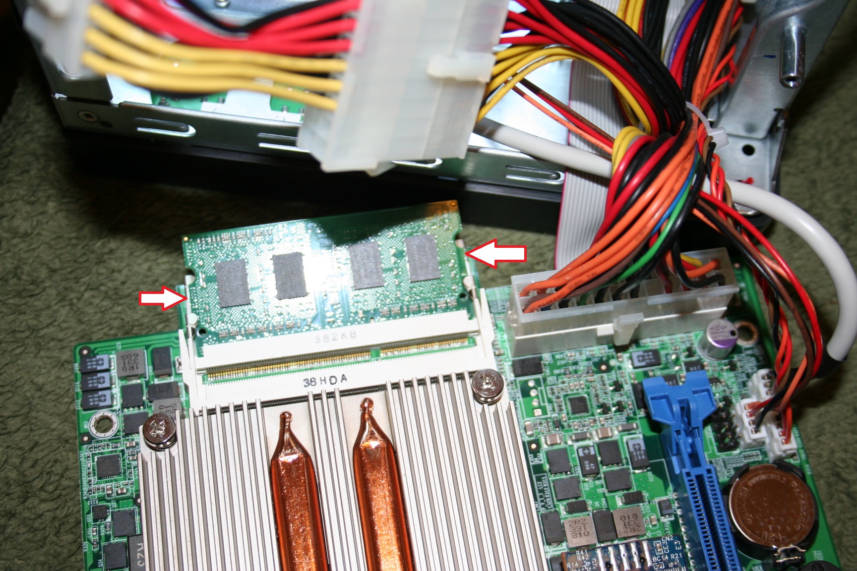
13.
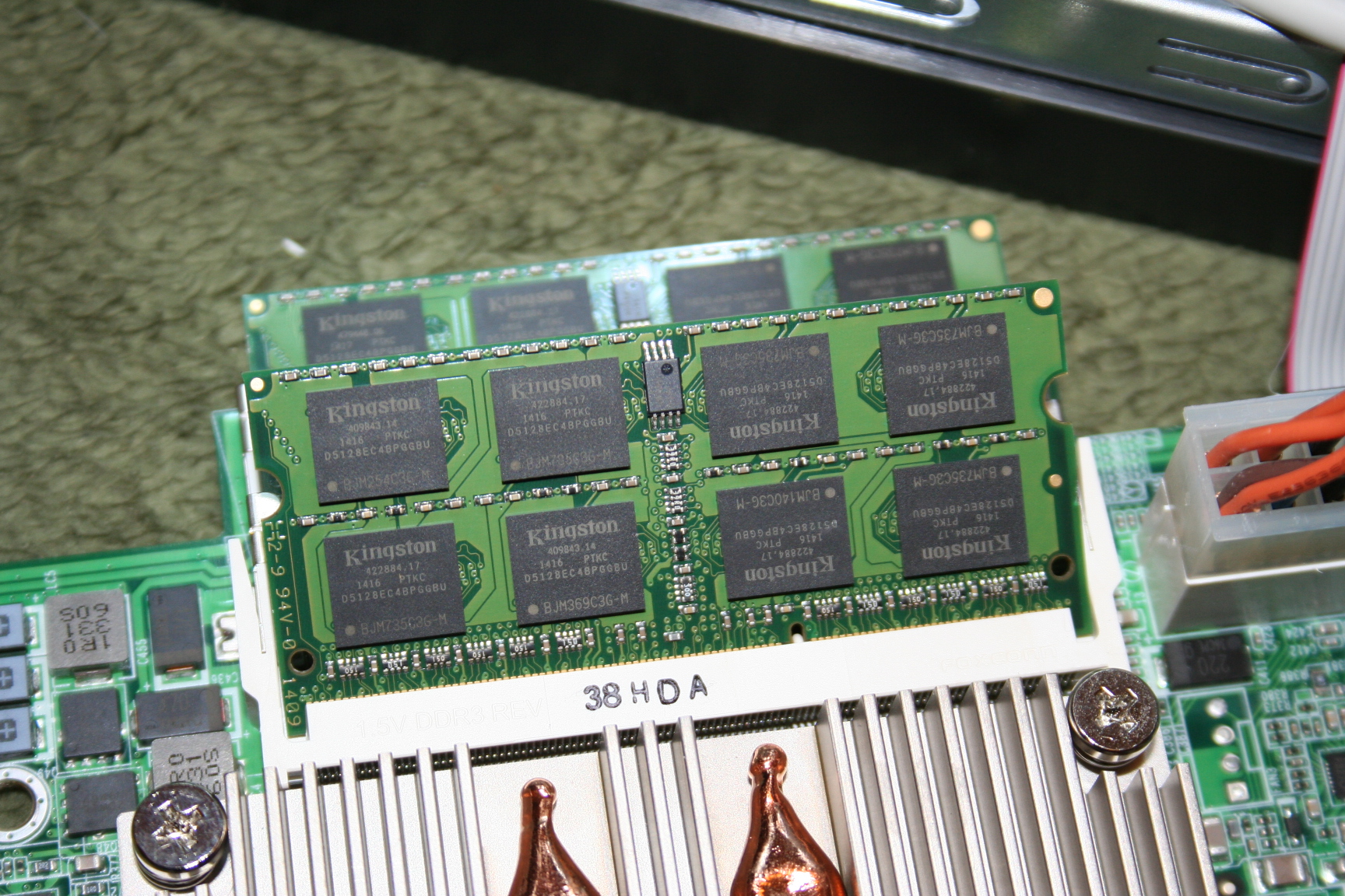
Gently remove the dimm(s)
by moving each of the metal tabs outward until the dimm releases and then
move the dimm up to a 45 degree angle and remove.
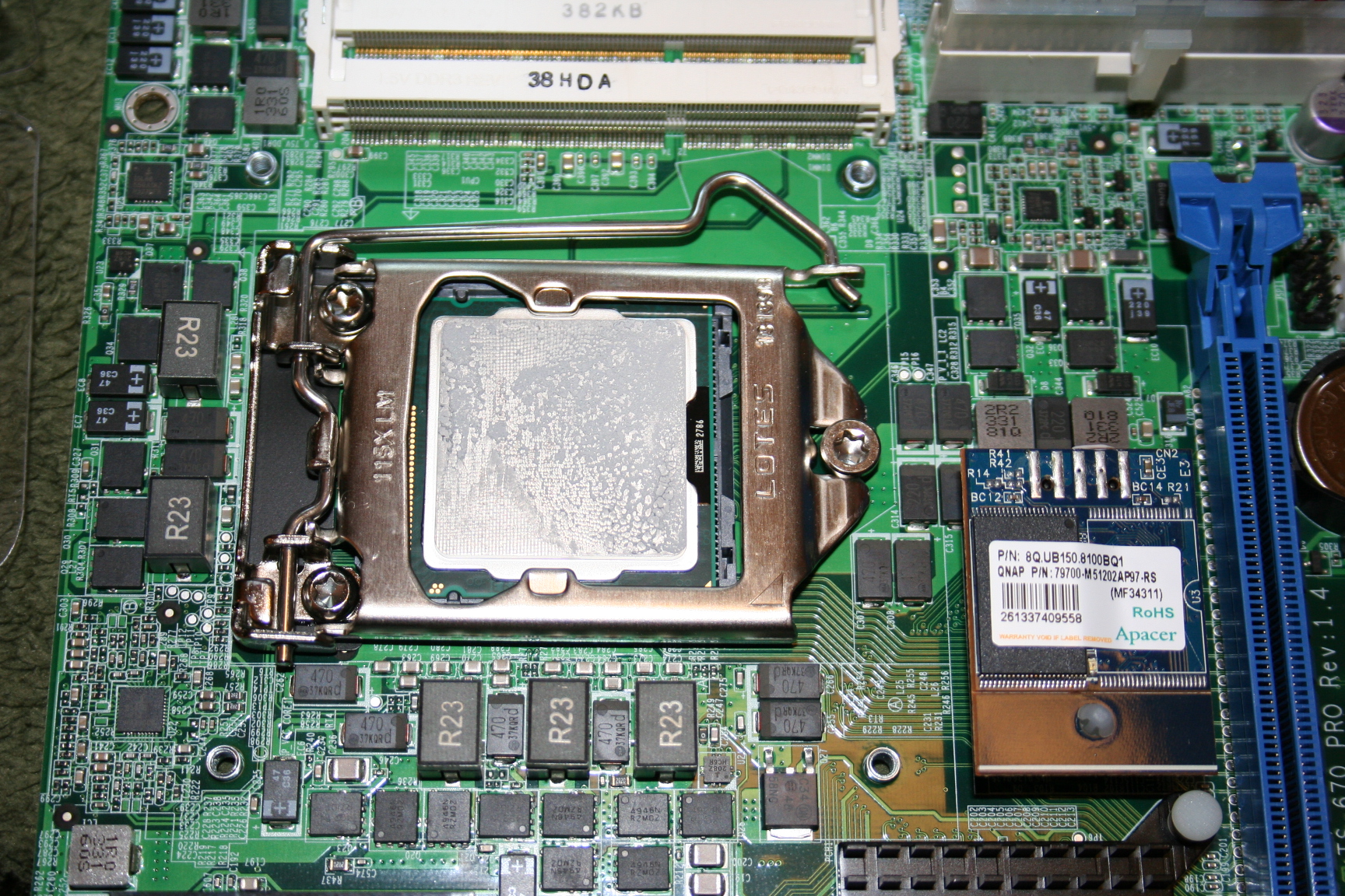
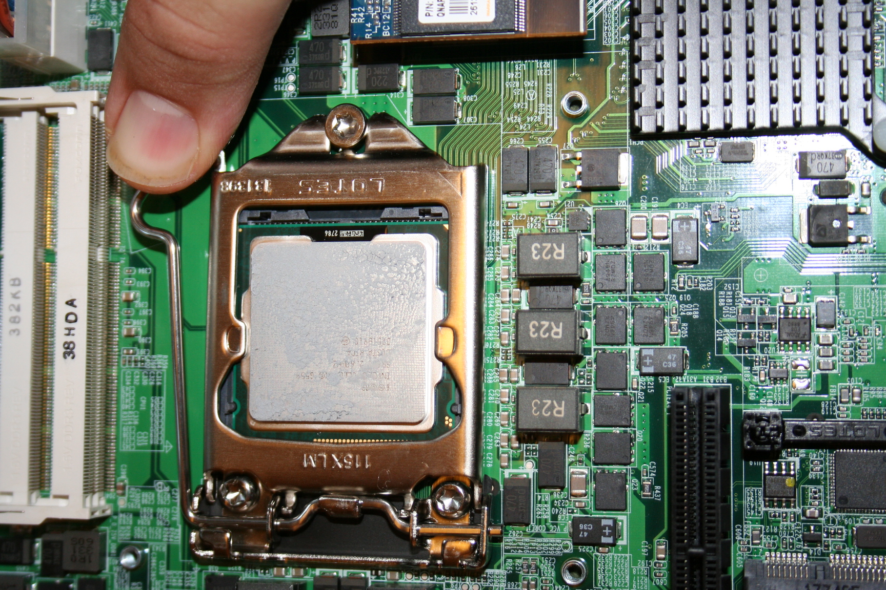
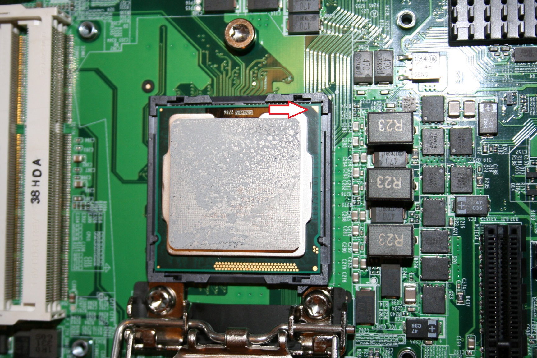
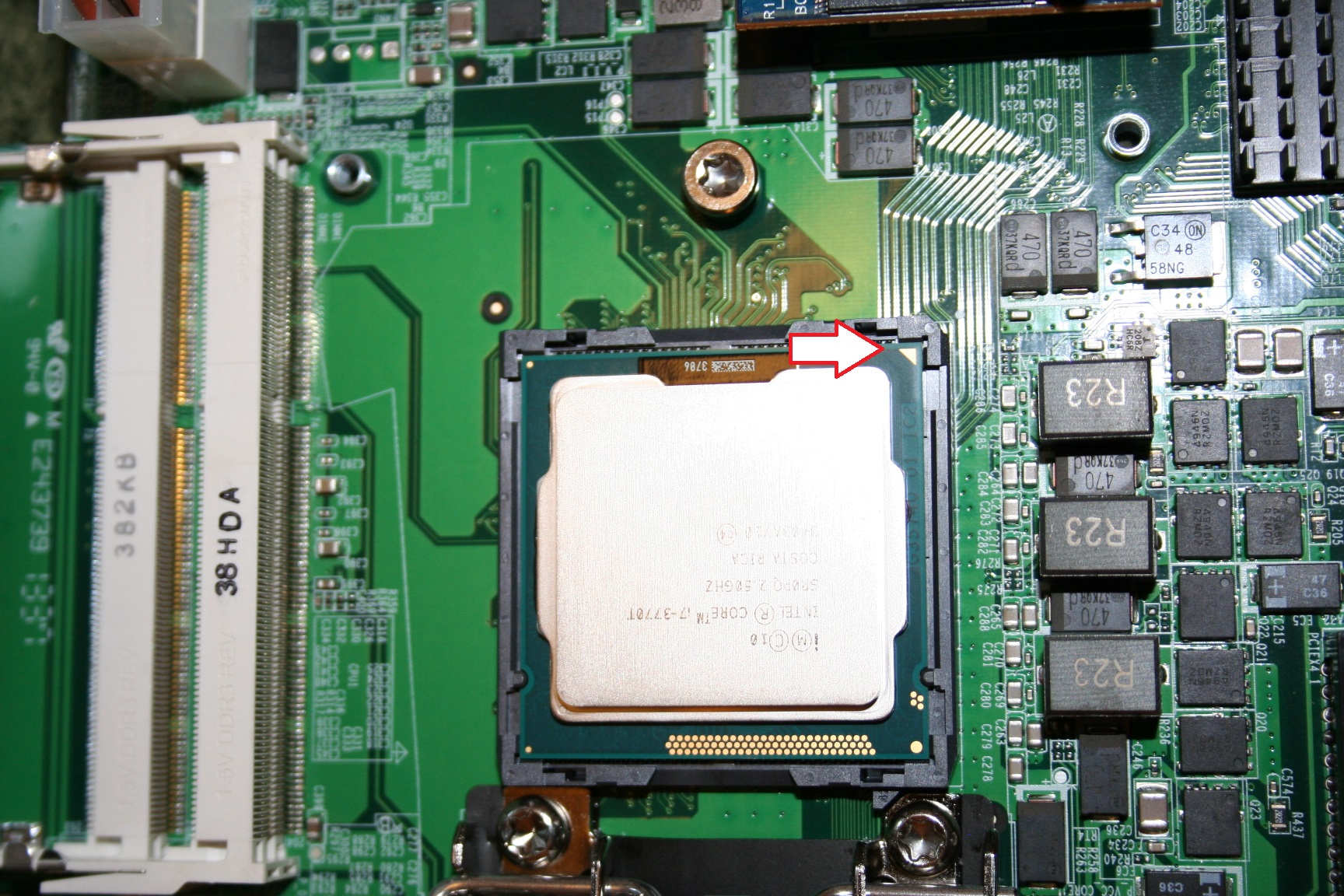
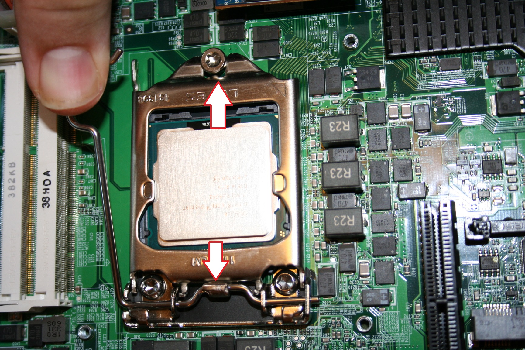
16. Push the retention lever down and then move it from under the frame of the cpu holder and then lift if up to allow you to release the cpu holder.
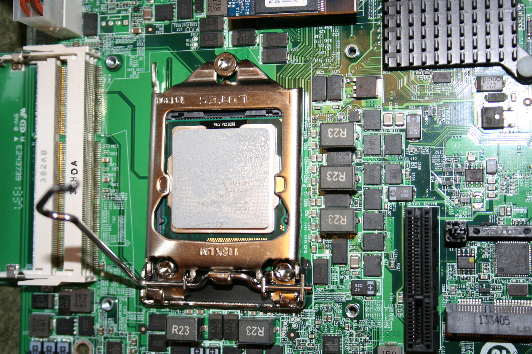
18. Replace the retention bracket. Make sure the front of the bracket is hooking under the screw and the back of the bracket as the retention bar in place. Then push the retention bar down and slip it back under the retention frame.
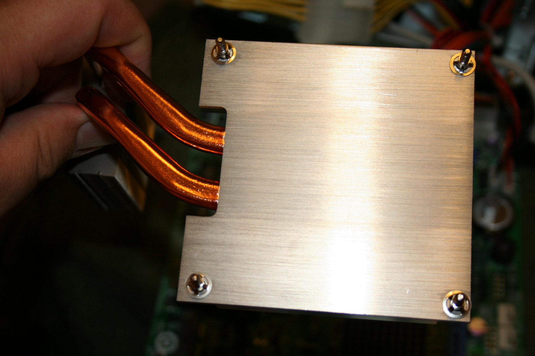
19. Clean the surface of the heat sink. Using ArctiClean solution works really well. I misplaced my solution so I used a few paper towels and that worked fine.
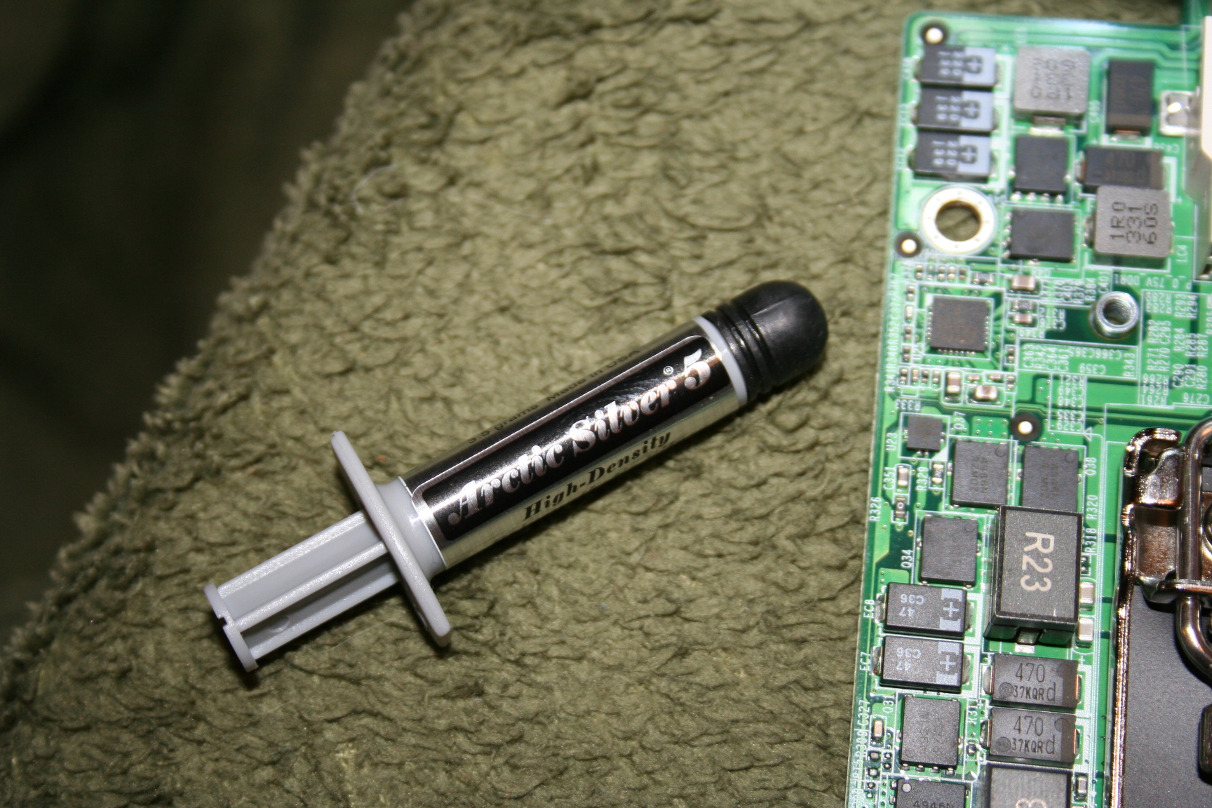
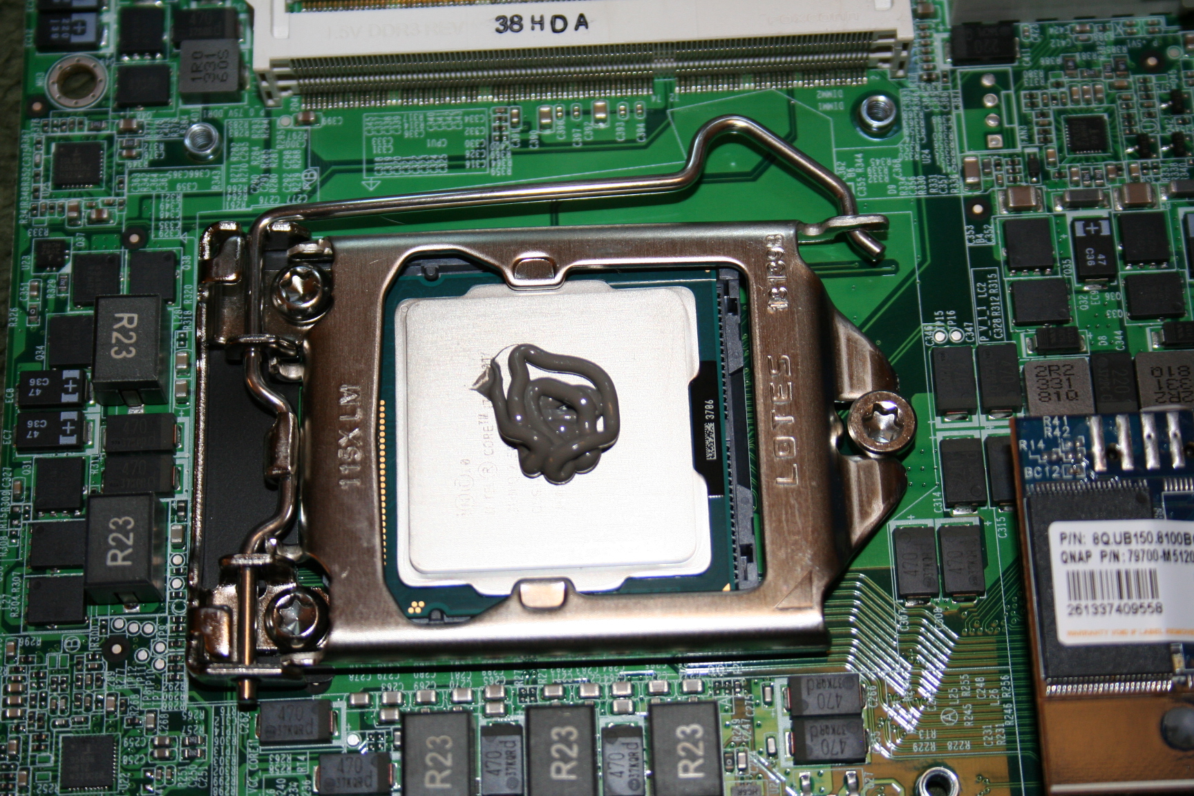
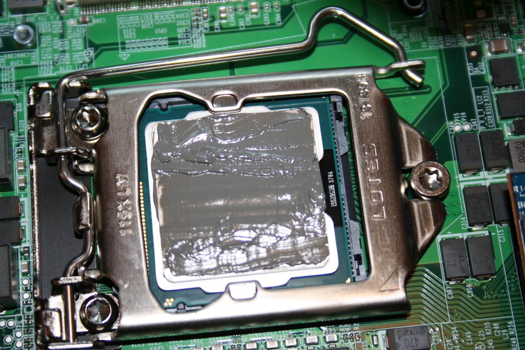
21. Using a small firm piece of plastic, or razor blade (I used the top cover edge of my Kingston memory kit) to spread the grease around to cover the entire cpu. You want the layer as thin as possible while covering the whole cpu.
22.
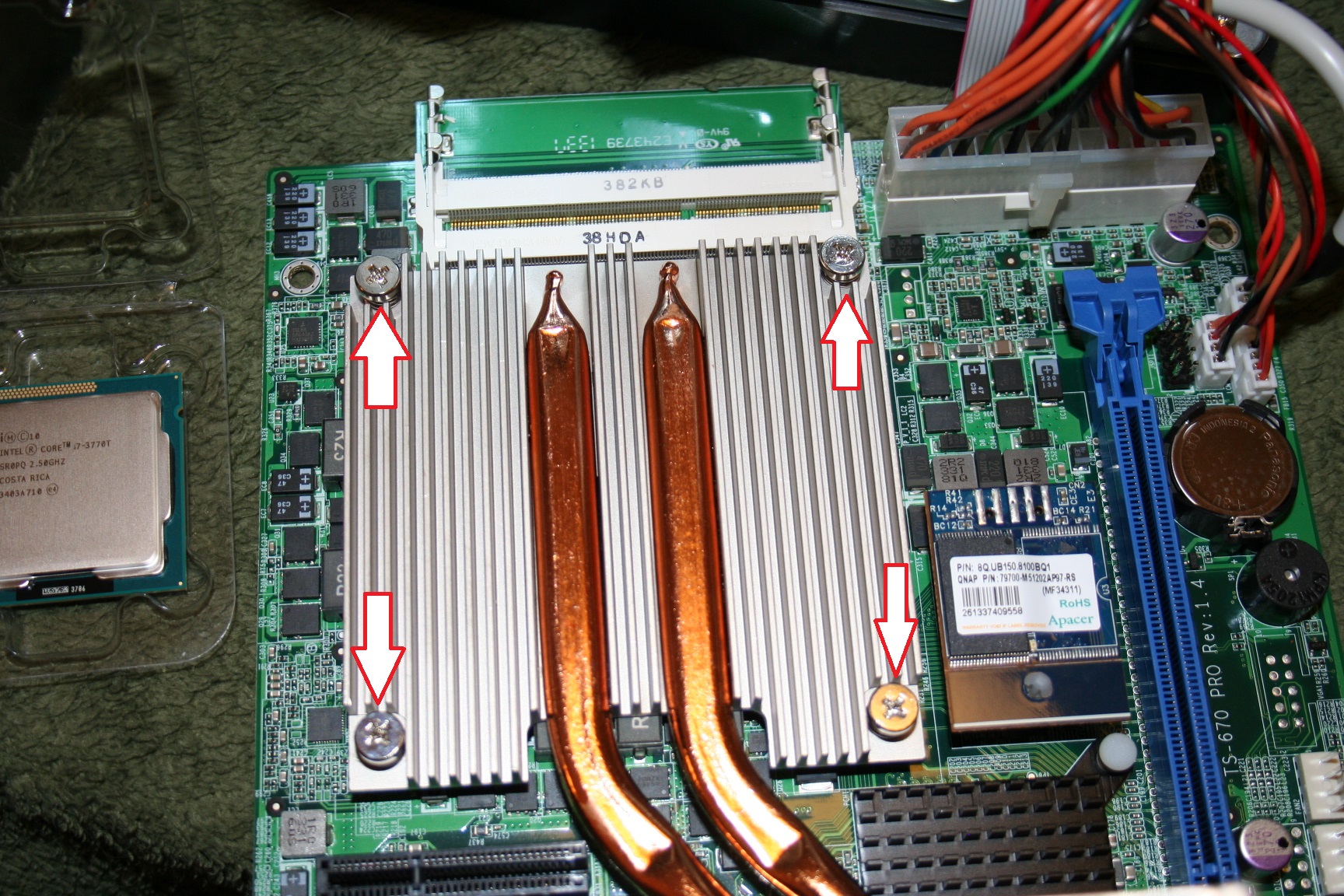
Place the heat sink back on top and screw in the
screws. Screw them in a pattern of
opposite each other and start with screwing them in half way and then all the
way, but do not just screw them in starting in one corner and working your way
around. If you do the screws
opposite each other you will get a better bond between the cpu and the heatsink.
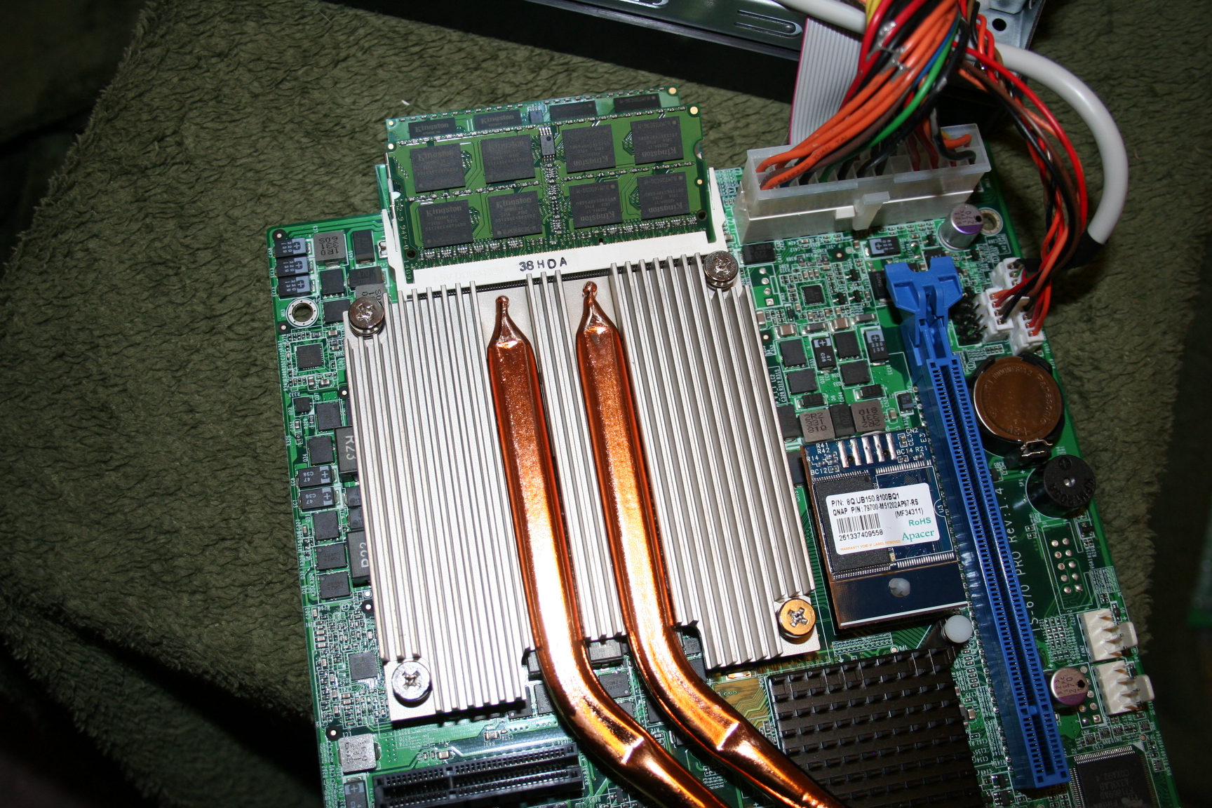
23. Insert the new dimms into their sockets by inserting them at a 45 degree angle until the contacts are all the way in and then press them down to lock them into the socket, one after the other.
24.
Start assembly by reversing your steps.
25.
Return the motherboard, plastic guard and screw
the motherboard into place.
26.
Return the backplane and screw it in with the
heat sink.
27.
Plug the power supply back into the back plane.
28.
Thread the fan connector back through the chassis
and screw the back cover back on.
29.
Plug in the network card and screw in the
retention screw
30.
Put the power supply back in place and screw in
the power supply.
31.
Place the cover back on the chassis and screw in
your final 3 screws
GOTO:
You can see the
testing I did before I did the upgrade here